Slit Scan
1. What is Slit Scan?
This photographic technique, developed in an era before digital technology existed, captures the changing contours and shapes of a subject over time by sequentially combining images taken through a slit (a narrow gap). It is sometimes used to photograph moving subjects or while moving the camera.
The image below is from Wikipedia.
It is famous for its use in the “Stargate” from 2001: A Space Odyssey (see image below).
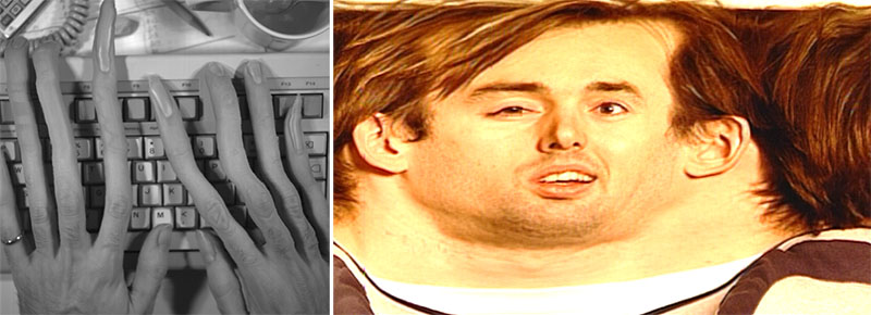
The image below shows the filming techniques used for the “Stargate” scene, as described in “4 Ways 2001: A Space Odyssey Was a Visual-Effects Pioneer.”
In addition to its use in video, there are many examples of its application in photography and art as a visual medium that captures changes over time (see reference). The photo-finish technology used in the Olympics and horse racing a few decades ago was also an application of slit-scan technology (see reference). Since photocopiers are a type of scanning device, they are similar to slit-scan technology, and there are examples of its application in artworks (see reference).
References)
- Special Effects Techniques Used in 2001: A Space Odyssey—Slit Scan
- YouTube - The History and Science of the Slit Scan Effect
- Applications of Slit Scan
- EXTENDED TIME THROUGH SLIT-SCAN PHOTOGRAPHY
- Making a Slit-Scan Camera – Prototype
- Slit Scan with the OM4 the “Coffee grinder”
- It’s kind of mysterious! The beautiful bands of color captured by slit scan - slit camera -
- How to Create the ‘2001’ Slit Scanning Effect with Digital Tools
- FORM+CODE TRANSFORM: SLIT-SCAN
2. Expressive Techniques Derived from Slit Scan
In recent years, the integration of digital technology with slit scan has given rise to more sophisticated techniques. The video below uses “time displacement” technology; although this differs from the original slit scan technique, this type of expression is also referred to as “slit scan.” Please refer to the URL below for the definition of slit scan.
Reference: Video slitscan/time displacement: How does it work?
In this exercise, we will introduce both the techniques mentioned above and those shown in the video below.
The following video works begin using slit-scan techniques at the 1-minute mark.
Examples of how to use the Slitscan plugin in After Effects.
3. Reference Tutorials
This exercise refers to the following tutorial videos.
4. SlitScan Representation 1
4.1 Goals
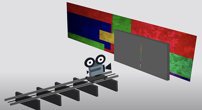
Here, we will experiment with the representation shown in the figure below.
4.2 Preparation
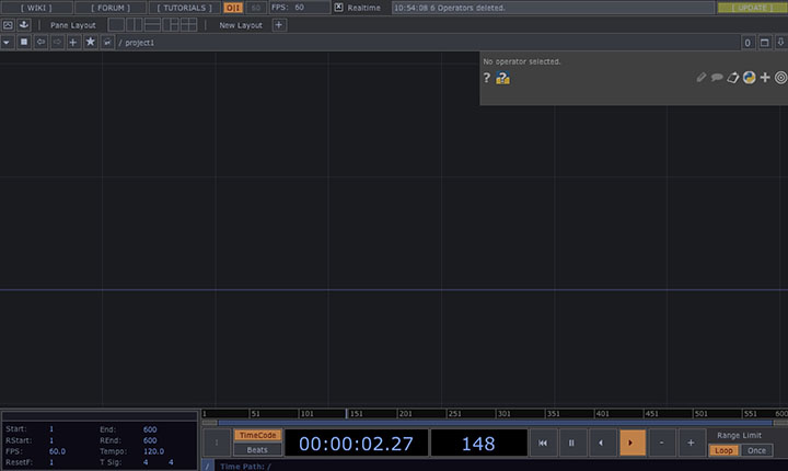
After launching TouchDesigner, delete the Startup Operator and close the Palette.

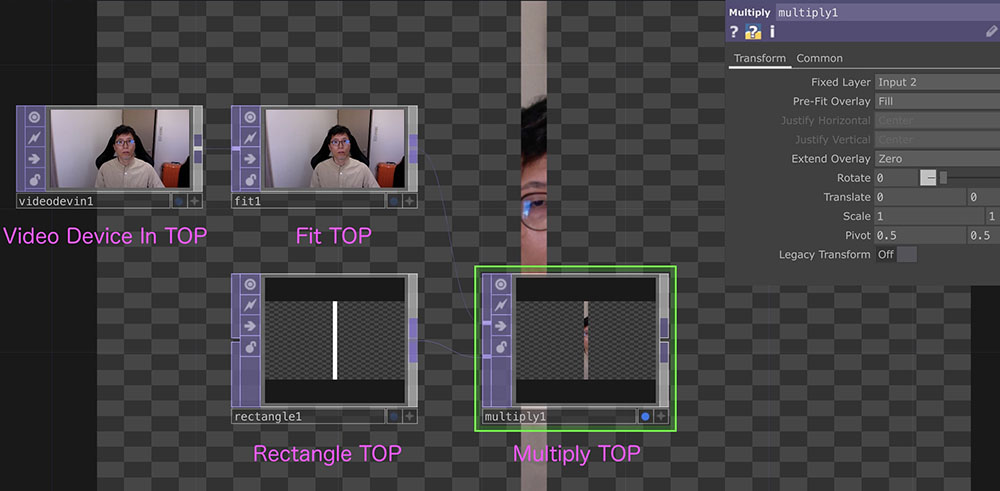
4.3 Slit Images
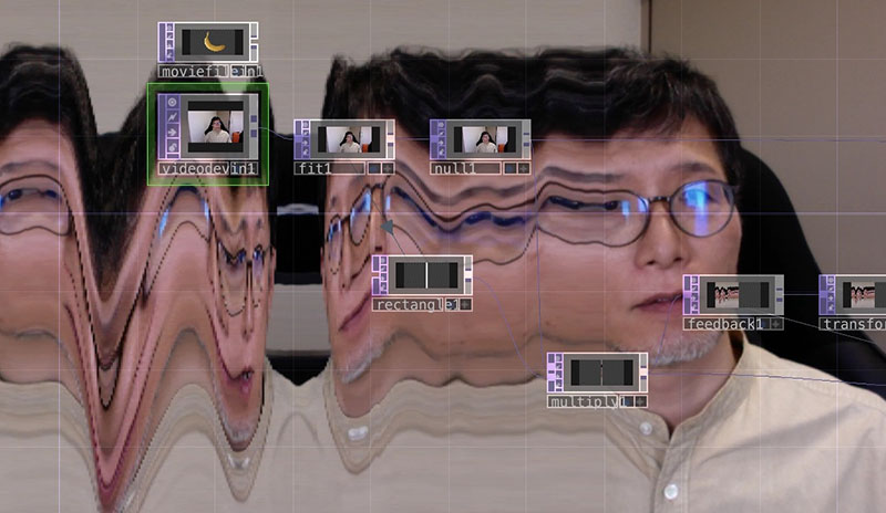
The following operators are used to generate slit images from the camera input images.
-
Video Device In TOP
- Video In tab - Device: Select Camera Input
-
Fit TOP
- Common tab - Resolution: 1280 x 720 *Resolution supported by the free version
-
Rectangle TOP
- Rectangle tab - Size: 0.03 x 1 *Specified with the image width set to 1 pixel
- Common tab - Resolution: 1280 x 720
-
Multiply TOP (Multiplication Mode Composition)
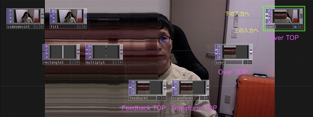
4.4 Feedback Effect
Add the following operators to configure the parameters.
-
Feedback TOP
- Connect from Multiply TOP
-
Transform TOP
- Transform tab - Translate X: -0.001
- Common tab - Input Smoothness: Nearest Pixel
- Common tab - Viewer Smoothness: Nearest Pixel
- *Note: Selecting “Interpolate Pixel” will cause the slit image to change over time due to interpolation.
-
Over TOP (over1)
- Drag and drop onto the Feedback TOP
-
Over TOP (over2)
- Connect Over TOP (over1) to the upper input
- Connect Fit TOP to the lower input
If you connect operators independently in an “island” configuration and then connect them all together, the image size may end up being 4:3 (a bug?). In that case, start by wiring from the operator where the image size is displayed correctly, and add the others one by one.
5. SlitScan Representation (2)
5.1 Goals
Here, we will experiment with the representation shown in the figure below.
5.2 Preparation
After launching TouchDesigner, delete the Startup Operator and close the Palette.
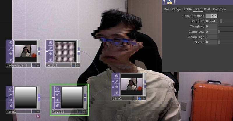
5.3 Operator Connection and Configuration
Connect the operator as shown in the figure below and configure the parameters.
-
Video Device (Top)
- Device: Select the camera you want to use
-
Texture 3D TOP
- Cache Size: 256
- Step Size: 4
-
Ramp TOP
- Type: Vertical
-
Level TOP
- Apply Stepping: ON
- Step Size: Approximately 0.02 *Slice width
-
Time Machine TOP
- Black Offset: Approximately -150 *Affects the time offset for each slice
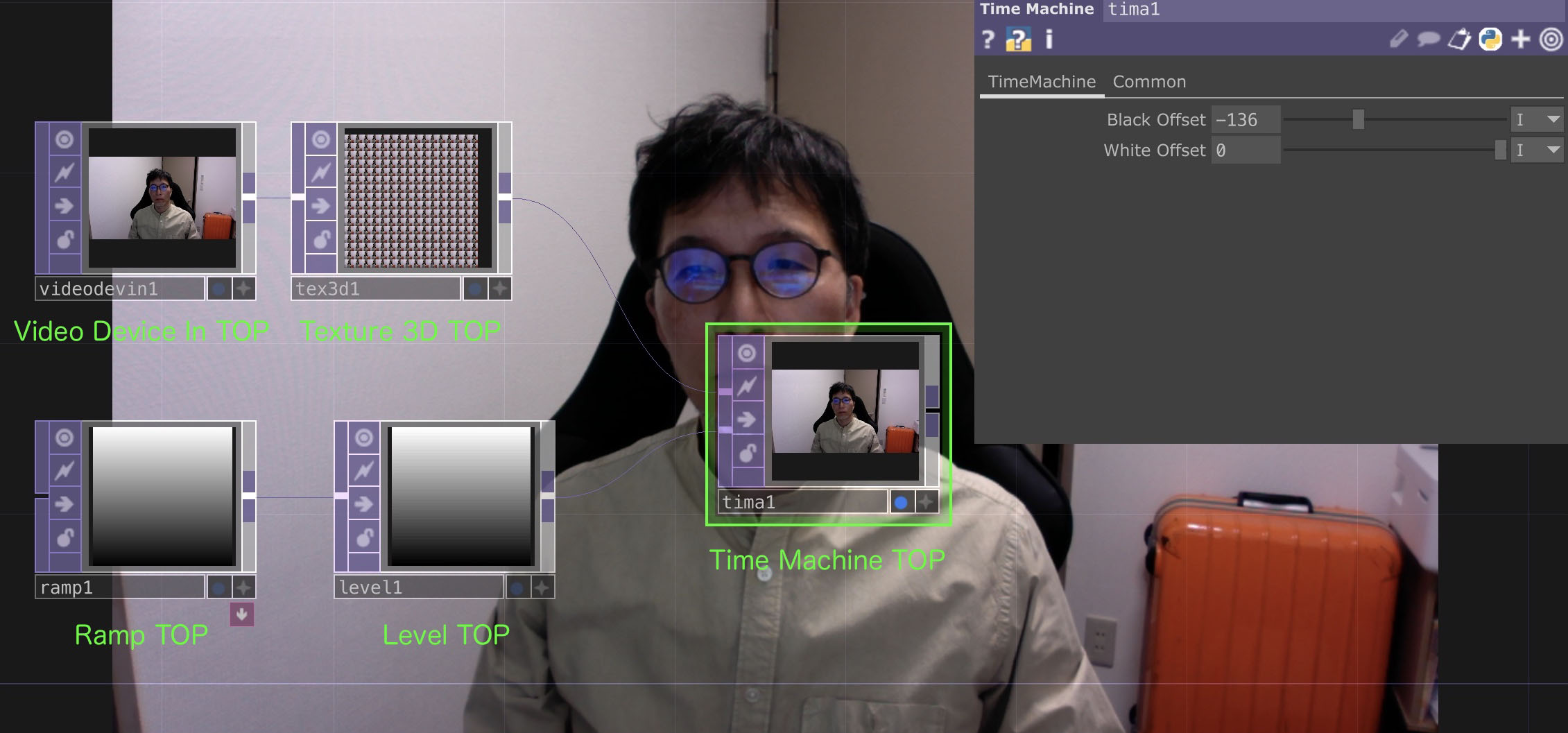
This allows you to create a visual effect where moving parts appear to be sliced. Since you can change the slice direction using the “Type” option in Ramp TOP, it’s worth experimenting with this and other parameters to see what happens.