TouchDesigner + Azure Kinect DK
1. Introduction
The goal here is to use the Azure Kinect DK to control an avatar of myself created through body scanning. While this is still in the experimental stage and not yet complete, I’d like to share the progress so far.
Current Status and Challenges
- While there are examples of experiments using the original Kinect and Kinect V2, there are few case studies involving Azure Kinect.
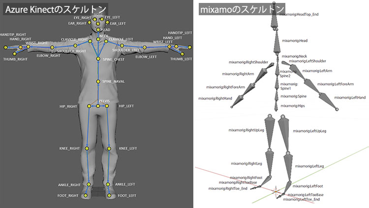
- Because the skeleton structure of Azure Kinect differs from that of the original Kinect and Kinect V2, the same rigging structure cannot be used.
- We experimented with upper-body motion by adjusting the mapping of the Mixamo model’s skeleton, but this is impractical because the Armature structure itself is different.
- Ideally, it is necessary to re-rig the model using the same structure as the Azure Kinect skeleton.
2. Websites Used as References
- Using Azure Kinect in TouchDesigner to animate custom models created in Blender
- YouTube - Kinect Azure - StickMAN (TouchDesigner)
- YouTube - Kinect V2 and TouchDesigner: How to Rig a Character in Blender
- YouTube - TouchDesigner Kinect TOP Tutorial 1 (Uncut Recording)
- Azure Kinect Body Tracking Joints
- Trying out Azure Kinect
3. How to Use the Azure Kinect Operator (for Image Analysis)
1. Kinect Azure Home
*Operators without “Azure” in their names are for the original Kinect and Kinect for Xbox 360.
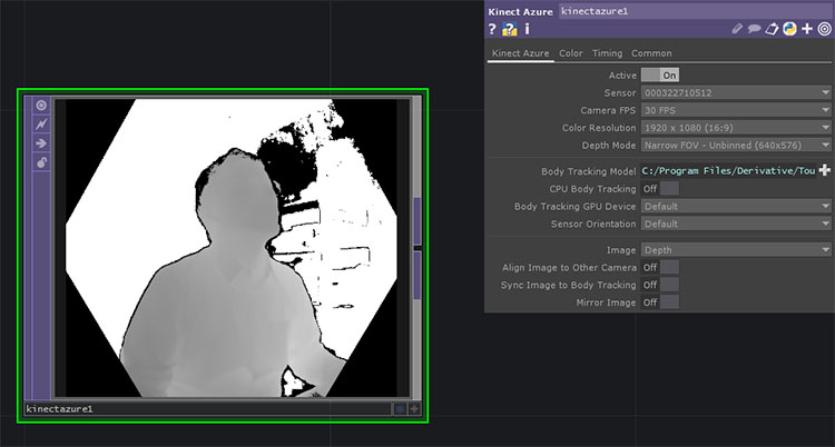
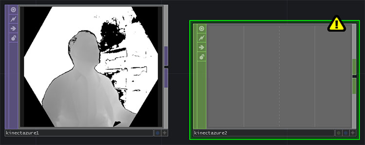
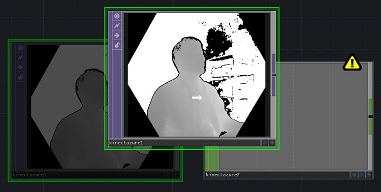
If you add the Kinect Azure TOP while the Azure Kinect is connected, it will be recognized immediately (see figure below). If you connect the Azure Kinect after launching TouchDesigner, select the serial number from the Sensor drop-down list in the Parameters window.
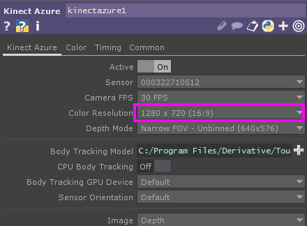
Since the maximum resolution in the TouchDesigner Non-Commercial edition is 1280 x 1280, change the “Color Resolution” parameter in Kinect Azure TOP to 1280 x 720 (16:9).
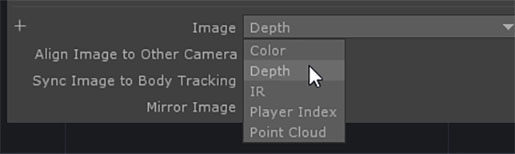
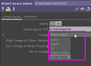
By default, the “Image” parameter is set to “Depth”. You can change it to the following options.
- Depth (Depth Camera)
- Color
- IR (Infrared)
- Player Index
- Point Cloud
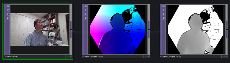
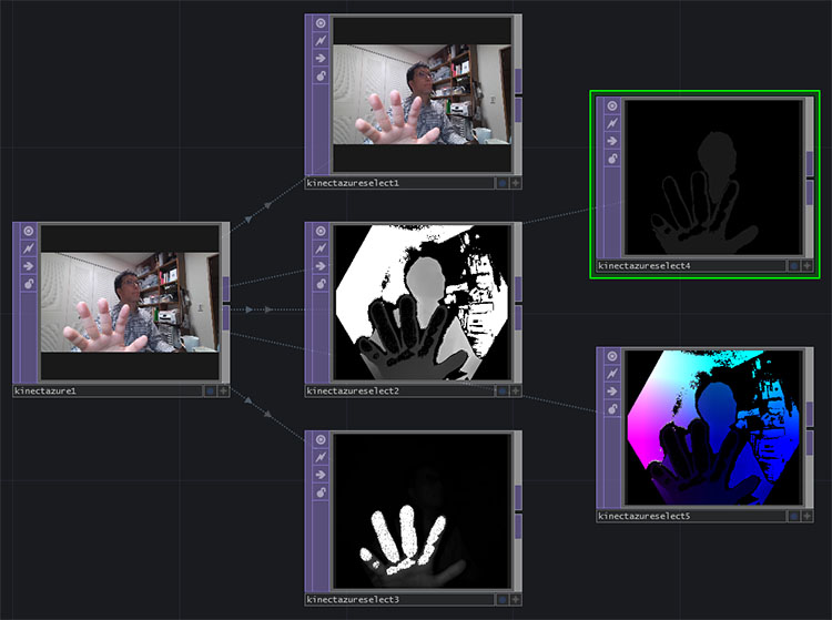
From left to right: Color, Point Cloud, and Depth views.
② Kinect Azure Select TOP
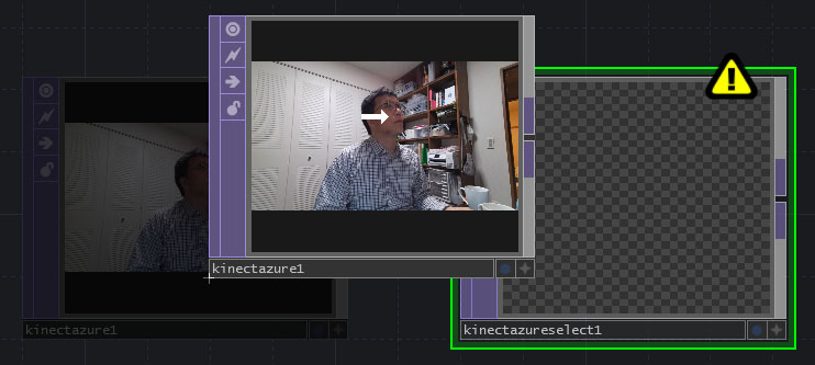
Add a “Kinect Azure Select TOP,” then drag and drop the “Kinect Azure TOP” onto the “Kinect Azure Select TOP.” This process is sometimes referred to as “nesting the Kinect Azure TOP within the Kinect Azure Select TOP.”
The point cloud is displayed in Kinect Azure Select TOP.
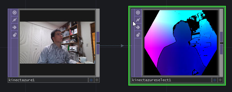
You can switch the display from the “Image” parameter.
By using multiple Kinect Azure Select TOP units, you can view multiple display states simultaneously.
4. How to Use the Azure Kinect Operator (for Body Tracking)
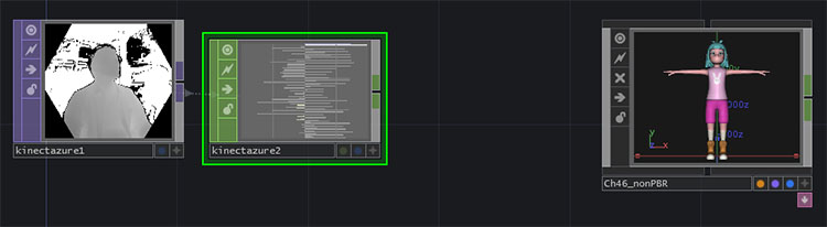
Add Kinect Azure TOP and Kinect Azure CHOP.
Drag and drop the Kinect Azure TOP onto the Kinect Azure CHOP.
Motion data is loaded into the Kinect Azure CHOP.
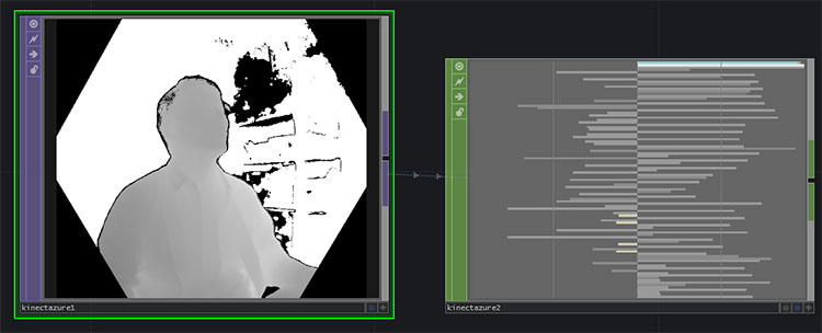
Since there is a large amount of data, zoom in to view it.
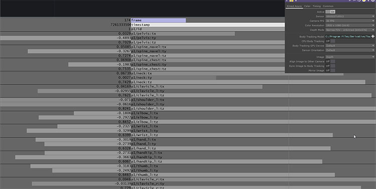
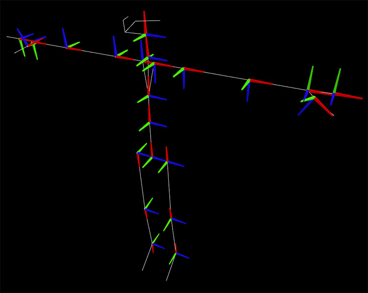
The 99 data points shown in the table below have been received.
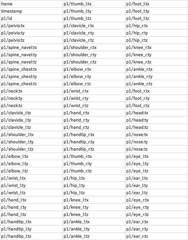
The data above corresponds to the joint coordinates of the skeleton shown in the figure below, including the pelvis, spine, neck, and clavicle (joints from Azure Kinect Body Tracking).
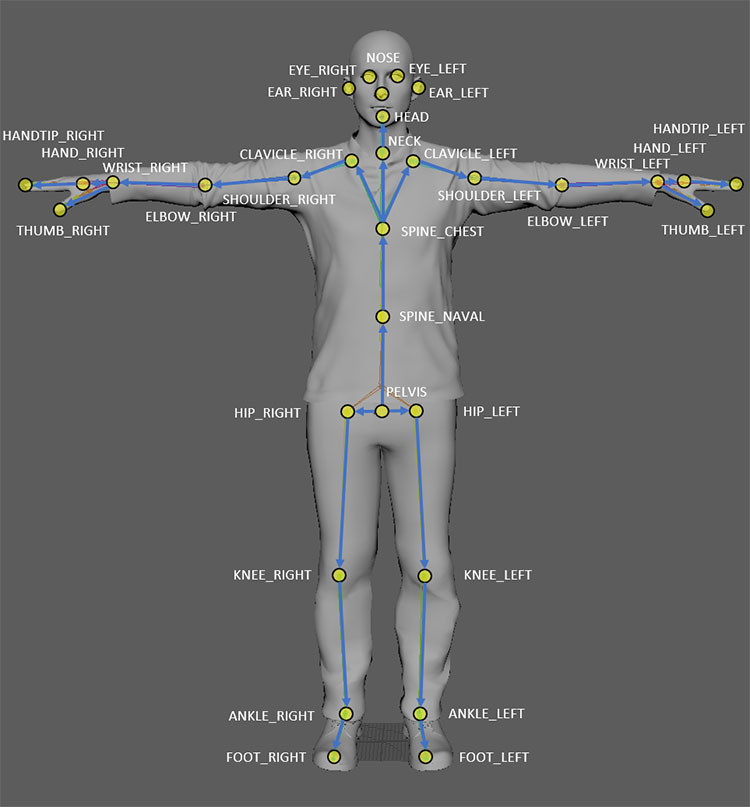
A unique joint coordinate system is formed based on the position and orientation of each joint.
5. Applied Knowledge 1: Value, Sample, Channel
- Channel: Labels for Value and Sample
- Value: The smallest unit of data handled by a CHOP
- Sample: A data structure consisting of multiple Values
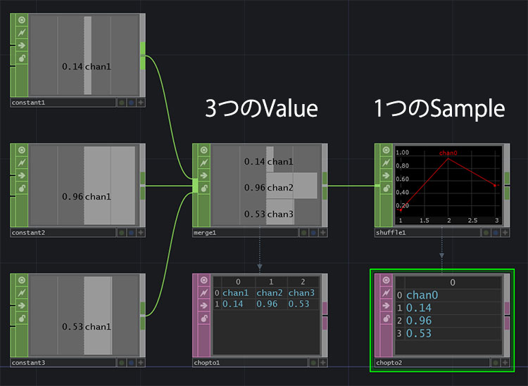
- Shuffle CHOP: Converts multiple Values into a Sample (Method: Swap Channels and Sample)
To handle large amounts of data at once in TouchDesigner, you need to convert it from the Value data structure to the Sample data structure before processing it. By using Sample, you can perform data processing efficiently, such as reordering or merging samples. In general programming terms, Value is similar to a variable, while Sample is similar to an array.
As shown in the figure below, at the “Value” stage, each of chan1, chan2, and chan3 contains a single value. After converting them to “Sample” using the Shuffle CHOP, chan0 contains all three values.
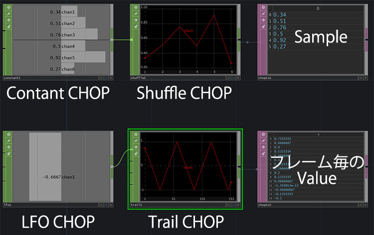
As shown in the figure below, “Sample” is displayed as a graph, so be careful not to confuse it with the change in “Value” over time.
Reference URL
- Special CHOPs You Often Forget
- Shuffle CHOP - TouchDesigner Japanese Documentation
- TouchDesigner CHOP Shuffling Demystified
6. Applied Knowledge (2): Instancing
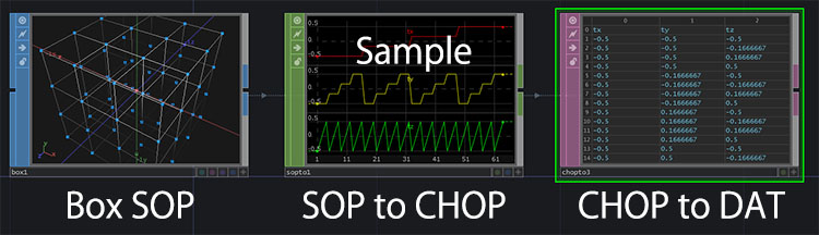
Box Section
- Box SOP, Divisions settings, Display Options (vertex display)
- SOP to CHOP (sample data format)
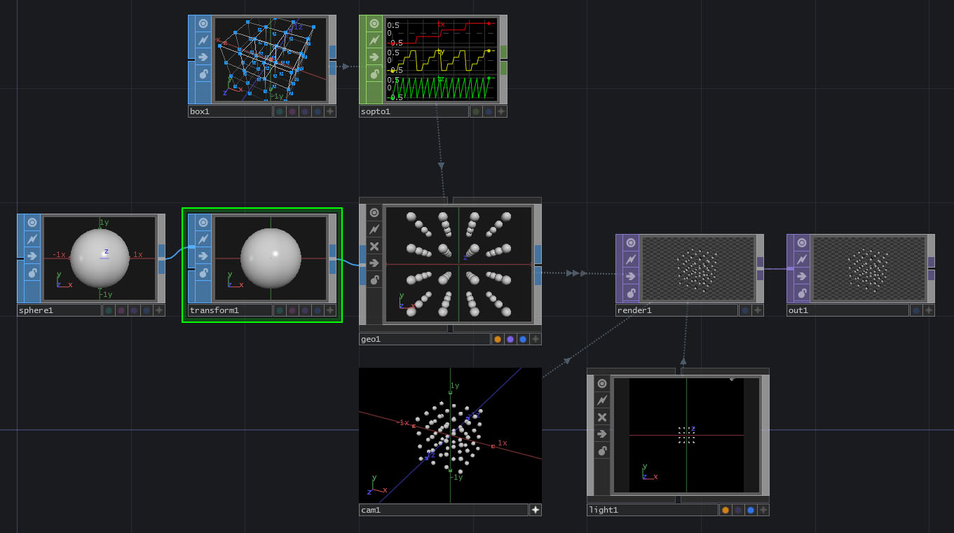
The area around the Sphere
- Sphere SOP
- Transform SOP
- Geometry COMP
- Camera COMP
- Light COMP
- Render TOP
- Out TOP
- Geometry COMP, Instancing: ON
- Drag and drop the SOP to CHOP into the Geometry COMP; Params: Default Instance OP (check this), Translate X: tx, Translate Y: ty, Translate Z: tz
- Transform’s Uniform Scale: 0.1
- Activate the Camera COMP and rotate the view to check
For reference
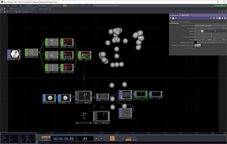
7. Experiment 1: Sphere Instancing
Instance and display spheres at the skeleton’s joint positions.
Further instructions will be provided during class.
- Select the Channel Names for the CHOP: *tx (ty, tz)
- Shuffle CHOP Method: Swap Channels and Samples; Use First Sample Only: ON
- You may rename each sample to x, y, and z
Download the following data and run the experiment.
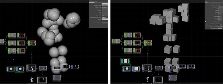
Let’s try changing the scale of the Sphere or converting it to a Box SOP.
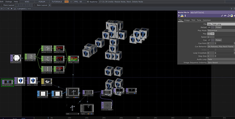
The image below shows a further modified version of TMU Man.
8. Experiment 2: Skeleton for Kinect Azure (by gormonboza) Project
1. Downloading the Project File
The original source is a forum post on TouchDesigner
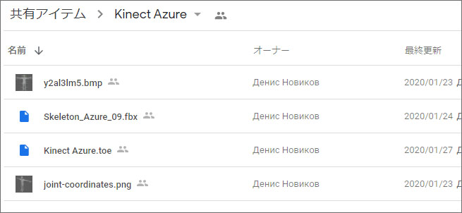
We will use the data published by gormonboza on Google Drive. There are four files listed below, but only the top two are required for the program to run. The remaining two are identical to the skeleton images published on the Azure Kinect website.
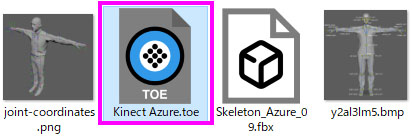
- Kinect Azure.toe
- Skeleton _Azure_09.fbx
- y2al3lm5.bmp
- joint-coordinates.png
Download the necessary data from Google Drive at the URL below.
2. Launching a Project File
Double-click Kinect Azure.toe to launch it. Since Skelton_Azure_09.fbx will also be loaded, you need to place it in the same directory.
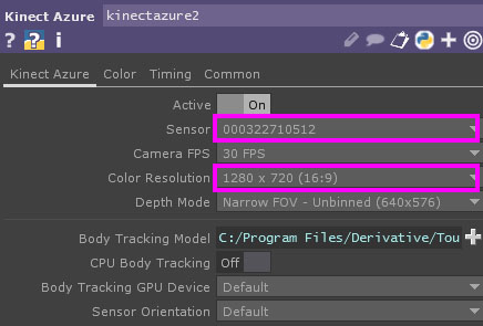
3. Configuring Kinect Azure TOP
Configure the following two items.
- Sensor: Select the Azure Kinect serial number from the drop-down list
- Color Resolution: Select 1280 x 720 (16:9) *Non-Commercial Edition
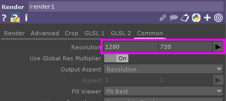
4. Configuring Render TOP
- Set the resolution to 1280 x 720 (16:9) *Non-Commercial Edition
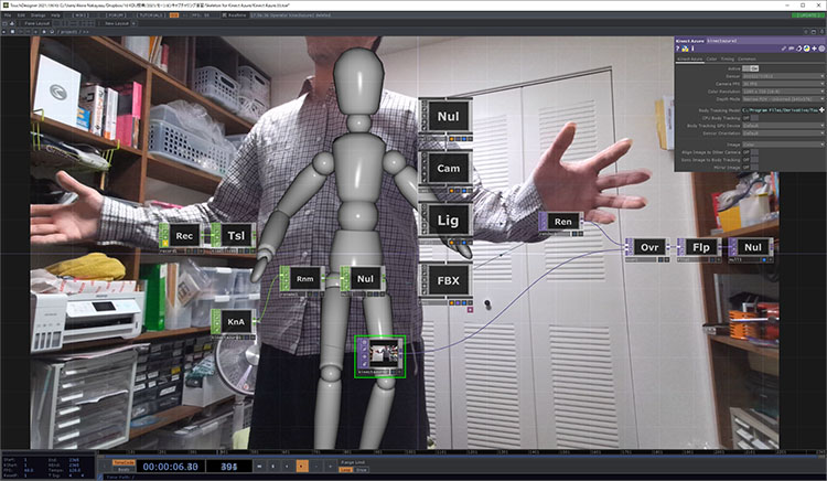
As shown in the figure below, you can animate the sample FBX character in real time.
9. Experiment 3: Animating a Mixamo Character
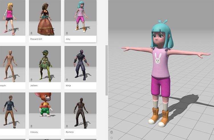
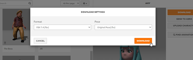
You can use any character. Download the file without animations using the settings below.
- Format: FBX 7.4 (Binary format is likely acceptable as well)
- Pose: Original Pose
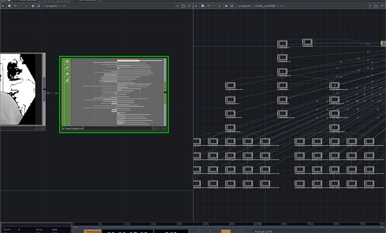
Drag and drop the FBX file into TouchDesigner. It will automatically be loaded as an FBX COMP.
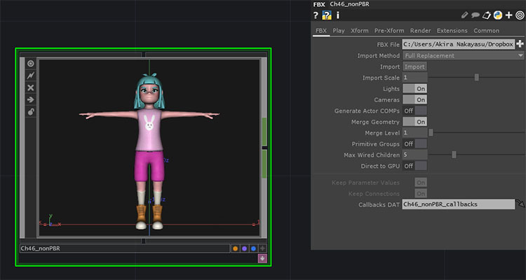
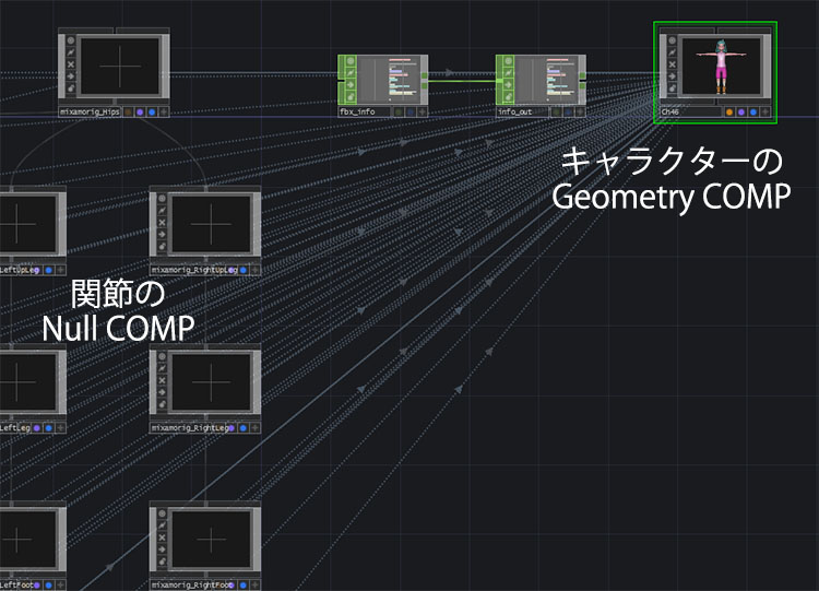
Zoom in, or press the ENTER key while FBX COMP is selected to enter FBX COMP.
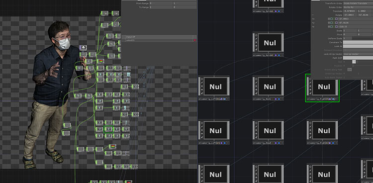
As shown in the figure below, you can see that numerous Null COMPs—which correspond to the skeleton’s joints—are linked to the character’s Geometry COMP.
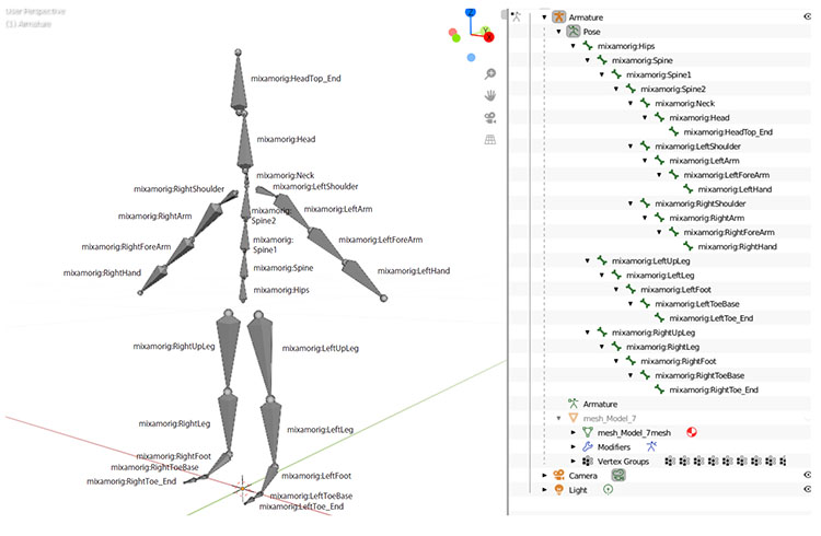
The figure below shows the results of analyzing the structure of an FBX file downloaded from Mixamo and imported into Blender. Since it was auto-rigged from human body scan data, it lacks finger joints, and the joint names are different.
For FBX files downloaded from Mixamo, while the joint structure is generally the same across characters originally created on Mixamo (though there may be some exceptions), the joint names differ from character to character. For this reason, it is not possible to simply swap out characters by replacing the FBX file.
To animate a Mixamo character using motion capture data from Azure Kinect, you must remap the joint data between the two skeletons—which have different structures—before passing it on. Ideally, you would re-rig the Mixamo character using the Azure Kinect skeleton structure, but we will not cover that here.
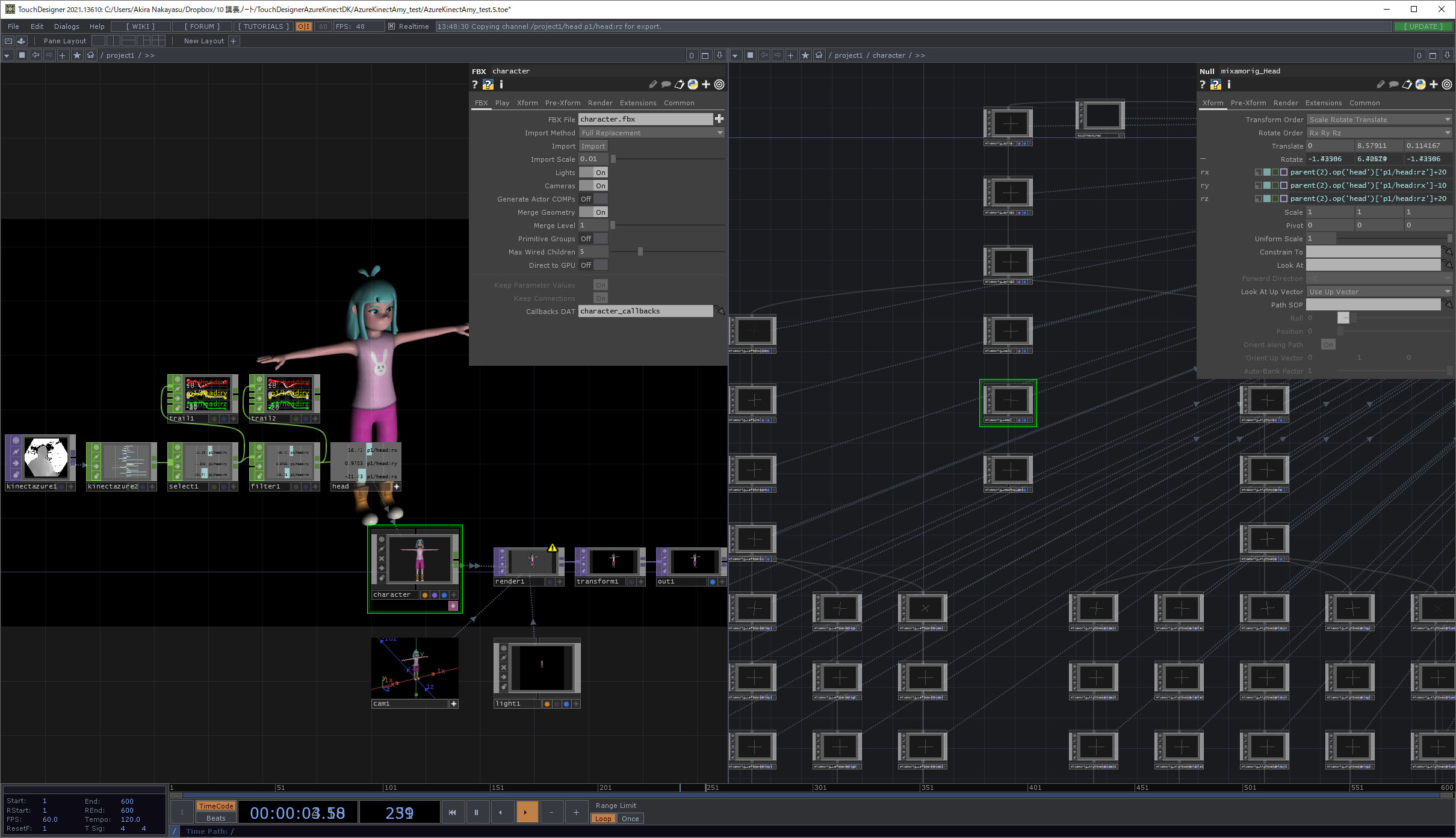
Here are the results of the experiment.
Feed the Kinect Azure TOP into the Kinect Azure CHOP.
This is still in the experimental stage. Below is a summary of the challenges.
- Analysis of the mapping between Kinect Azure CHOP data and the joint Null COMPs in the character FBX
- Analysis of rotation angles relative to the joint coordinate system
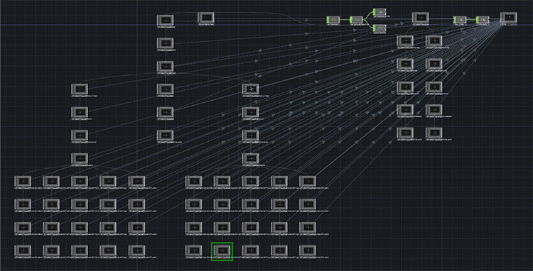
As shown in the figure below, split the screen into two sections and configure the setup so that the Kinect Azure CHOP is on the left and the contents of the FBX file are visible on the right.
Further details will be provided in class.
FBX Import Section
- FBX, Import Scale: 0.01
- Camera COMP
- Light COMP
- Render TOP
- Transform TOP, Background Color: 0, 0, 0, 1, Comp Over Background Color: ON (for black background)
- Out TOP
Azure Kinect Section
- Kinect Azure TOP
- Kinect Azure CHOP, Relative Bone Rotations: ON, World Space Positions: OFF
- Select CHOP, Channel Names: head, verify using the Trail CHOP if necessary
- Filter CHOP, Type: Gaussian, Filter Width: approximately 0.8, verify using the Trail CHOP if necessary
- Null CHOP
Parameter Linking in Motion Data
- Link parameters to the FBX “mixamorig_Head” (Null COMP)
- Azure Kinect → FBX
- rz → rx
- rx → ty
- ry → rz
- While linking each parameter, adjust the pose error using + and -.
Sample data: https://data.nakayasu.com/files/before2021/touchdesigner/AzureKinectAmy_test.zip
10. Experiment 4: Displaying a Point Cloud Using a Circle SOP Instance
This is a TouchDesigner-style implementation of the preview I was working on in Azure Kinect Viewer ***.
Sample data: https://data.nakayasu.com/files/before2021/touchdesigner/AzureKinectPointCloud.zip
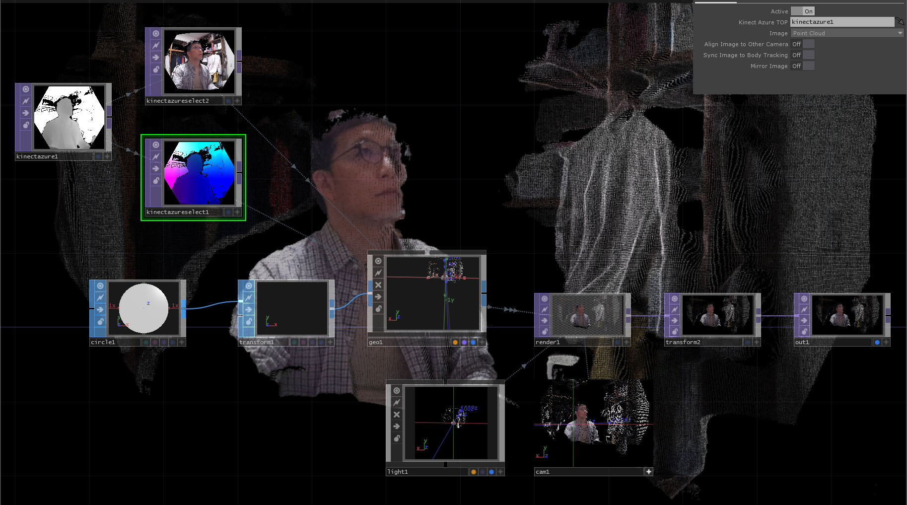
If used effectively, it can also be utilized as a visual medium.