TouchDesigner Basics
1. What is TouchDesigner?
A node-based visual programming environment developed and sold by Derivative, a Canadian company. It supports high-speed video processing and integrates with various devices such as Arduino, Kinect, Oculus, and lighting equipment, making it ideal for creating interactive content. It is widely used for a range of applications, from real-time performances such as projection mapping and live shows to media art. A NON-COMMERCIAL version is available for free for personal use, though it has limited functionality (e.g., output resolution of 1280×1280).
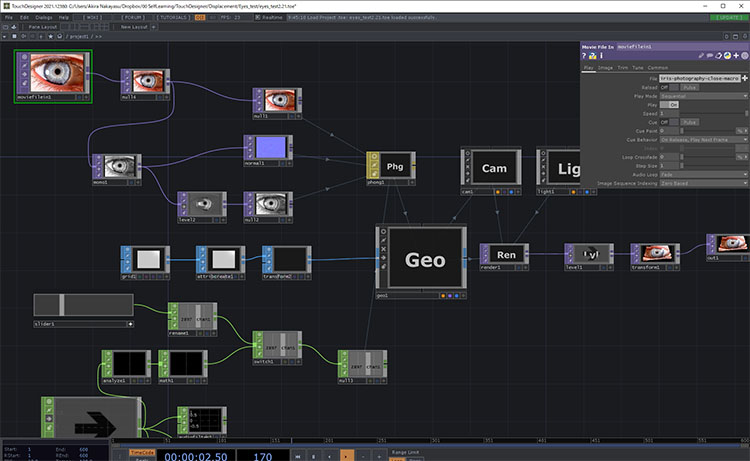
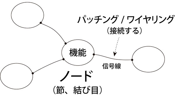
In node-based programming, programming is performed by connecting nodes with specific functions, as shown in the figure below. By using node-based tools that make it easy to understand the flow of processing, it has become easier for artists and designers to do their own programming.
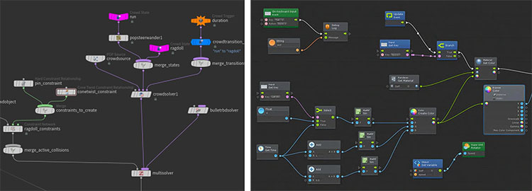
In addition to TouchDesigner, the number of node-based tools has been on the rise in recent years, including vvvv, Max, and Notch. While some, like TouchDesigner, are used as primary editors, others, such as Houdini (left image below: Nodes and Network), Blender, and Unity (right image below: Bolt), utilize node-based tools for specific functions.
Terminology varies from tool to tool. Below is a comparison of the terminology used in TouchDesigner and Max. This is based on my own research. The terms for signal lines are my personal designations.
TouchDesigner
Cycling’74 Max
- Node: Object
- Signal Line: Patch Cord
In TouchDesigner, in particular, connecting Operators with Wires is sometimes referred to as “patching” or “wiring,” or as “building a node network.”
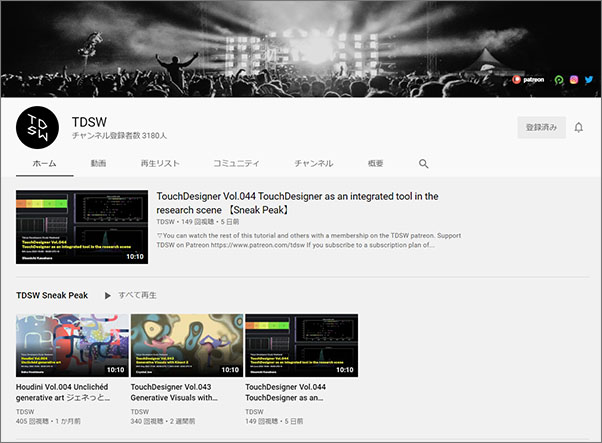
2. Works Created with TouchDesigner
Here, we present just a small selection of works created using TouchDesigner. Many more projects are featured in the Showcase section of the Derivative website.
3. The Benefits of Self-Study
I won’t go into detail here, but if you search for “TouchDesigner,” you’ll find plenty of articles. TouchDesigner is widely used among visual creators, and since there’s a wealth of information available in Japanese, you can learn it entirely online by combining web resources with YouTube tutorials.
TDSW (Tokyo Developers Study Weekend) offers a wide range of tutorials for visual creators, covering tools such as Touch Designer, Houdini, and Notch. Even beginners can learn step by step, and there are also many tutorials on advanced techniques.
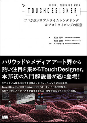
As of 2021, there are only two Japanese books available, but these two books alone are sufficient to master the subject, from the basics to advanced applications.
The TouchDesigner Bible for Visual Creators

Visual Thinking with TouchDesigner: Experts’ Secrets to Real-Time Rendering and Prototyping
4. Installation and Registration Instructions
This guide explains how to install the NON-COMMERCIAL LICENSE version of TouchDesigner. For detailed instructions, please refer to the on-demand video in the “Introduction to Digital Creation” series.
1. Creating a Derivative Account
Go to https://derivative.ca/, click MY ACCOUNT > CREATE NEW ACCOUNT to proceed to the REGISTER page (see image below), and enter the required information. Please note that you cannot use a USERNAME that has already been taken.
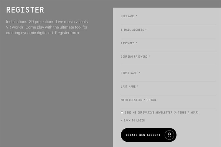
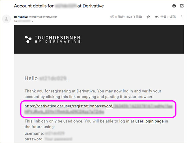
Even if you click the “CREATE NEW ACCOUNT” button at the bottom of the screen above, your registration is not yet complete. To finish the process, click the link in the confirmation email with the subject line “Account details.”
2. Downloading and Installing the Software
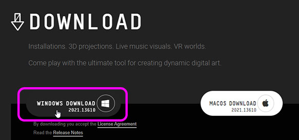
Click “GET IT NOW” in the upper-right corner of the Derivative website, then click “WINDOWS DOWNLOAD” on the DOWNLOAD page. Since the file is about 1.4 GB, it will take some time to download.
Once the download is complete, launch the installer and follow the on-screen instructions to install it.
3. Creating a Key (NON-COMMERCIAL LICENSE)
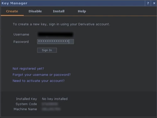
When you launch TouchDesigner, the Key Manager appears. Enter your username and password (see below) and click Sign In.
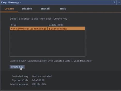
Click the “Non-Commercial” license (see below), then click “Create Key.” You only need to do this once; it will not appear the next time you launch the program.
You can create up to 10 keys per account. If you switch computers or similar, you can add more keys to accommodate the change. With a Non-Commercial license, once a key is created, it cannot be deleted.
*If you are unable to generate a key when launching the app, you may be able to generate one on the Derivative website using the Machine Name and System Code. For details, please visit the website below.
https://docs.derivative.ca/Creating_a_Key
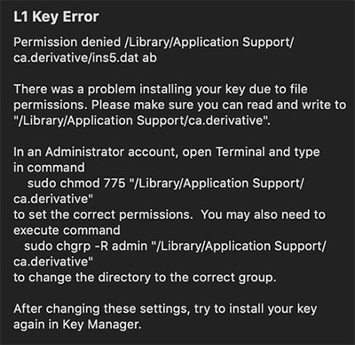
If an L1 Key Error (see below) occurs, reinstalling the software with administrator privileges will resolve the issue.
5. Starting/Shutting Down
1. Launch
Launch it using a desktop shortcut or by searching for the app.
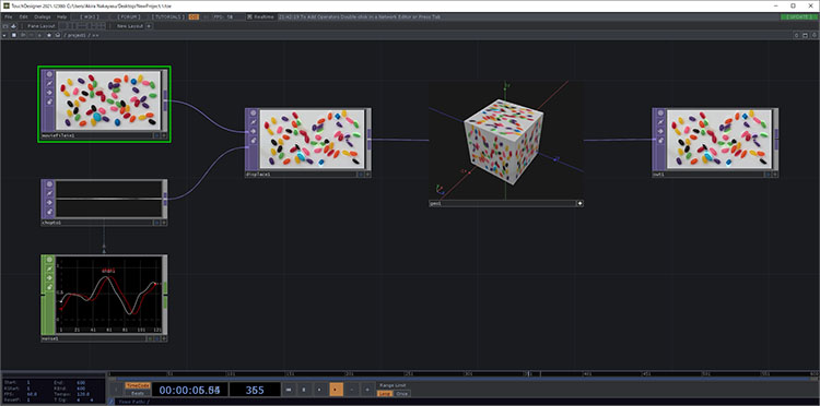
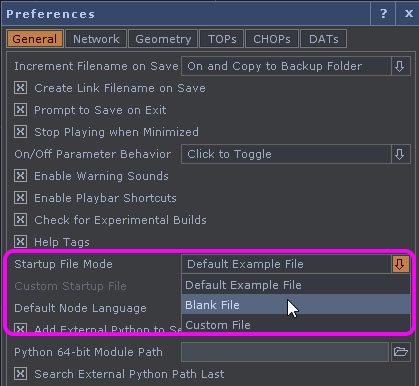
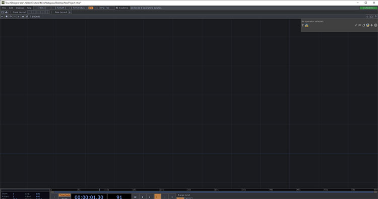
By default, a sample project (see figure above) is loaded, but you can start with a blank project by changing the settings under Edit > Preferences (see figure below).
2. End
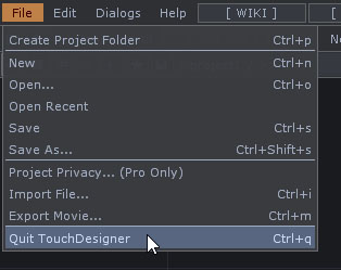
Click File > Quit TouchDesigner, or click the × in the upper-right corner of the window.
6. User Interface Overview
UI Overview
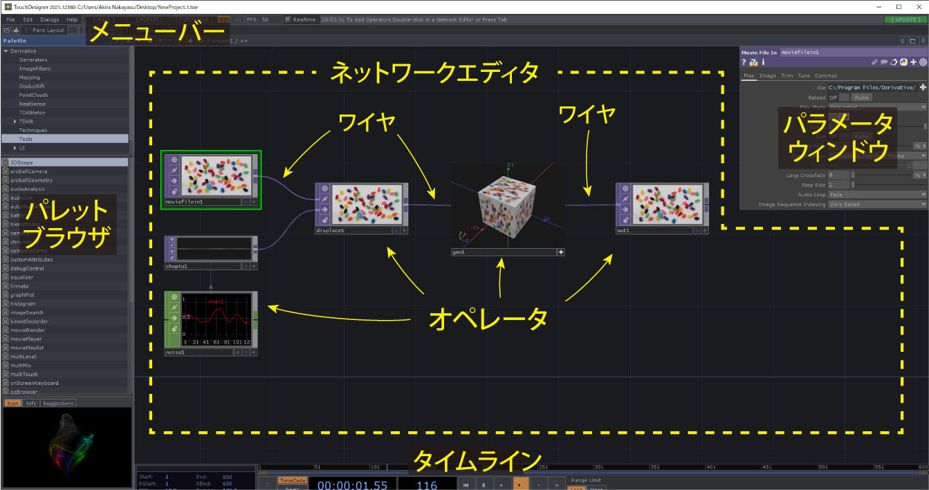
The basic programming process in TouchDesigner involves adding operators in the Network Editor and connecting them with wires. Beginners do not use the Palette Browser or Timeline.
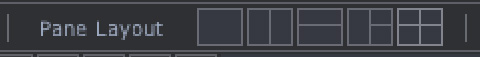
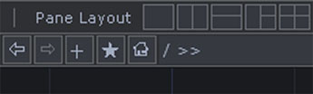
Pane Layout
In TouchDesigner, windows are called “panes,” and by default, the Network Editor is displayed in a single pane.
You can switch between different pane layouts using the “Pane Layout” option at the top of the UI.
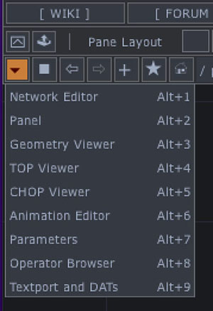
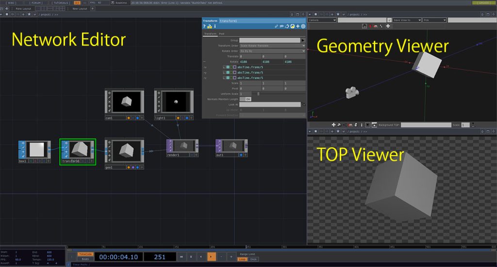
In each pane, you can select the editor or viewer to display from the menu that appears when you click the ▼ in the upper-left corner of the pane.
You can use various pane layouts depending on the project.
7. Working with Views
This section explains only how to use the Network Editor views. The operation of the operator will be covered later.
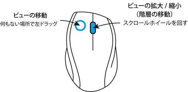
Keyboard shortcuts for view operations
- H key: Show full view of the Network Editor
- SHIFT+H: Enlarge the selected operator
If you zoom out too much, you’ll go back a level, so zoom in to return to the original level.
8. Introduction to the Operator
In TouchDesigner, you program using operators with various functions. Since there are many different types of operators, you’ll learn them gradually as you use them.
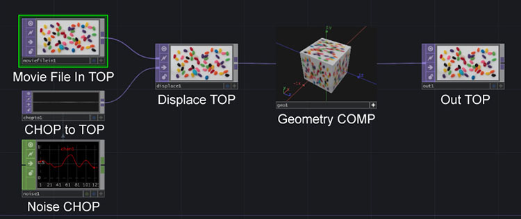
The sample project (see the figure below, second level) contains the following operators.
- Move File to Top
- CHOP to Top
- Noise CHOP
- Displace to Top
- Geometry COMP
- Out to Top
Operator Families (Types) and Types
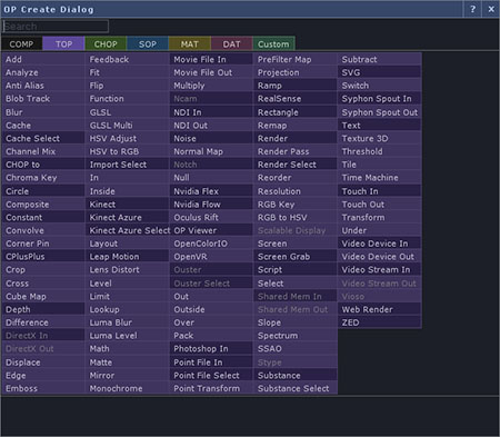
Display the OP Create dialog to verify. Press the Tab key or double-click in an empty area of the Network Editor.
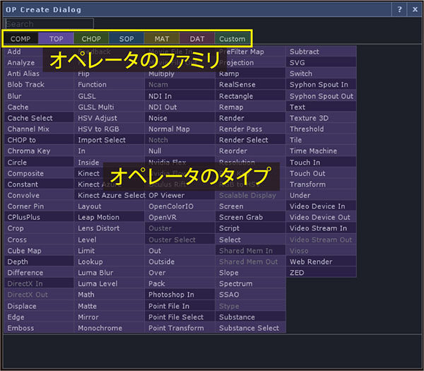

When you click the tab (see above), the operators are grouped by family, and various types of operators are displayed (see below). They are color-coded for easy identification.
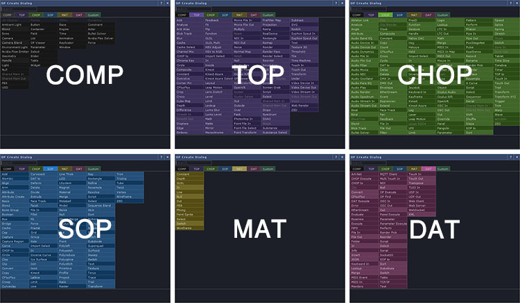
The following are the characteristics of the family.
COMPs (Components): UI, program structure, and 3D system construction TOPs (Texture Operator): For 2D image processing, including still images and video data CHOPs (Channel Operator): Numerical processing, calculations, and device I/O SOPs (Surface Operator): 3D object processing MATs (Material): 3D material and shader processing; used in conjunction with SOPs DATs (Data Operators): Scripting, data storage, and device input/output Custom: Registration of custom operators; not typically used unless you are an expert
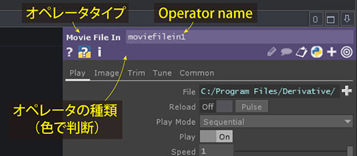
Checking the Operator Type (Parameter Window)
Each operator is assigned a unique name (which can be changed), and this name is used to refer to the parameter.
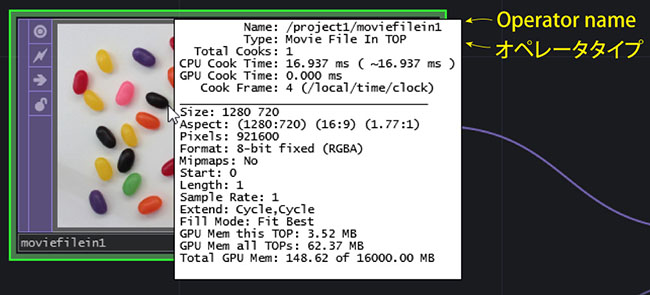
Checking the Operator Type (Info Display)
Click the middle mouse button in the Operator window to display the Info.
How to Address Operators
Operators are referred to by their “type name + family name.” For example, the Noise CHOP is called “Noise CHOP.” When an operator is available in all six types, such as Null, it is referred to as Null COMP, Null TOP, Null CHOP, and so on.
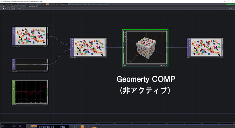
Active/Inactive
Operators can be either active or inactive. The Geometry COMP in the sample project is active by default.
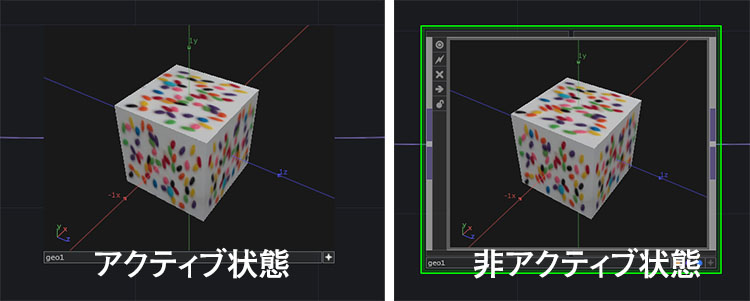
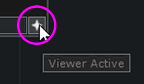
You can switch between them by clicking the + button in the lower-right corner of the operator.
The actions that can be performed while active vary by operator.
9. Hierarchical Structure
The Network Editor in TouchDesigner features a hierarchical structure, which simplifies complex combinations of nodes. The number of levels varies depending on the project’s structure and the types of operators used.
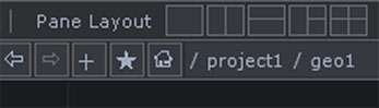
You can see your current position in the hierarchy in the diagram below the menu.
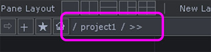
The hierarchy is indicated by “/” (slash). If “»” is displayed, it indicates that there is a lower level below it.
Navigating Between Levels (Mouse Wheel)
- Move up a level: Keep collapsing the Network Editor
- Move down a level: Keep expanding the Network Editor while an operator at that level is selected
Navigating Between Levels (Keyboard Shortcuts)
- Move up a level: u key
- Move down a level: With the operator containing the level selected, press the i key or the Enter key
Sample Project Directory Structure
The sample project consists of three levels. The first level, at the root (top level), contains the following three operators.
- Container COMP (Name: project1)
- Window COMP (Name: perform)
- Base COMP (Name: local)
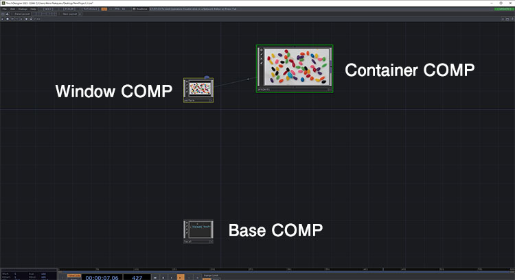
It is clear that the second level was the first to be opened and that it contains the Container COMP from the first level.
The second level contains TOP and CHOP, but these have no internal sub-levels. Since sub-levels exist only in Geometry COMP, click the “+” button in the lower-right corner of the operator to deactivate it. Select the operator and press the “i” key.
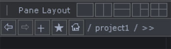
Since the third-level address does not contain “»”, we can see that there are no levels below it.
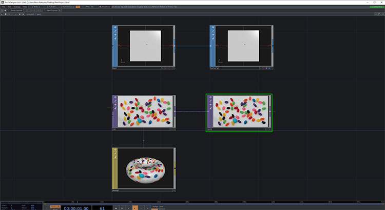
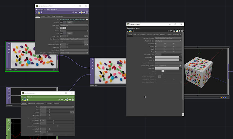
The third layer (within the Geometry COMP) contains SOP, TOP, and MAT, as shown in the figure below. Since the Geometry COMP can be used in various ways, its configuration is not always the same.
10. Parameter Window
You can use the Parameter Window to configure the parameters for each operator.
Display in a fixed position
In the sample project, it appears in the upper-right corner; selecting an operator changes the display to show that operator’s parameters. You can toggle the display on or off by pressing the P key.
Display at any location
You can display the Parameters window at any location by selecting “Parameters” from the context menu that appears when you right-click on the operator (when it is inactive).
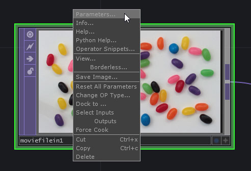
As shown in the figure below, you can also display multiple windows. The parameter window at any given position will remain displayed with the parameters of the original operator, even if you change the selected operator.
11. Operator Procedures
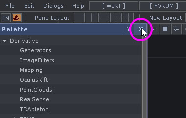
1. Close the Palette Browser
Since I won’t be using the Palette Browser, click the “X” shown below to close it.
2. Clear the Network Editor
When building a node, first delete all operators from the sample project, as shown in the figure below. Select all using Ctrl+A (or by dragging the mouse to highlight them) and press the Delete key to remove them.
3. Adding an Operator
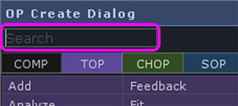
Double-click the Network Editor or press the TAB key to open the “OP Create” dialog.
You can easily find it by entering the name of the type you’re looking for in the search box of the “OP Create Dialog.”
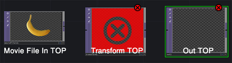
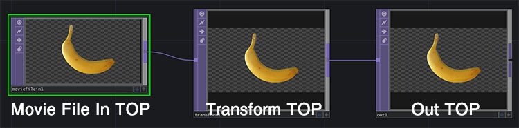
Add the following three operators to the TOP family.
- Movie File In TOP: Input of external images and video
- Transform TOP: Move, rotate, scale, etc.
- Out TOP: Output to the Window COMP, which is the final output destination
If the wires are not connected, an “Error” message will appear as shown below, but this is not a problem.
4. Selecting, Moving, and Deleting Operators
- Select: Left-click the mouse
- Select multiple items: Hold down the SHIFT key and left-click, or drag the mouse to highlight the items.
- Move: Drag the mouse while holding down the left button
- Delete: With the items selected, press the Delete key
⑤ Wiring
Operators can have outputs, inputs, or both inputs and outputs. By connecting (wiring) the outputs and inputs, you can transmit signals.
As shown in the figure below, drag from near the right port on the Movie File TOP and connect it to near the left port on the Transform TOP. You can also connect them in the opposite direction.
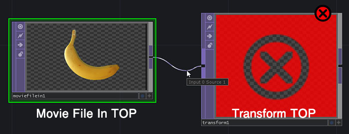
Follow the same steps to connect the output of the Transform TOP to the input of the Out TOP. The error will disappear, and a banana icon will appear on all operators.
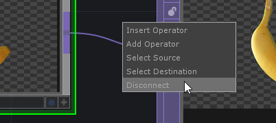
⑥ Removing the Wire
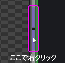
Right-click on the wire and select “Disconnect.”
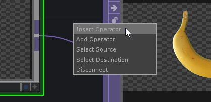
⑦ Insert Operator
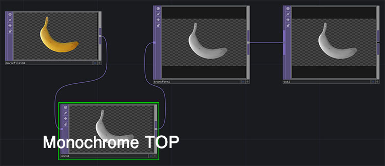
If you right-click on a wire and select “Insert Operator” from the menu, the operator will be inserted in the middle of the wire.
The figure below shows the Monochrome TOP installed.
⑧ Wiring as Operators Are Added
Right-clicking on the output section of an operator will immediately open the OP Create dialog. If you add an operator this way, it will be automatically wired. If it has already been wired, the action will be “Insert.”
12. Working with Parameters
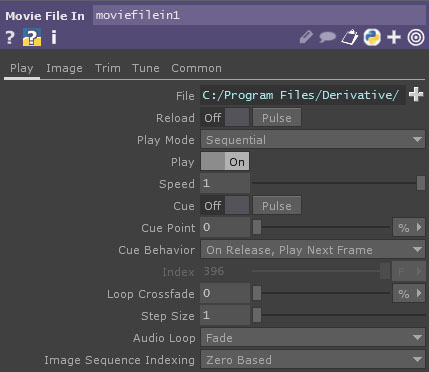
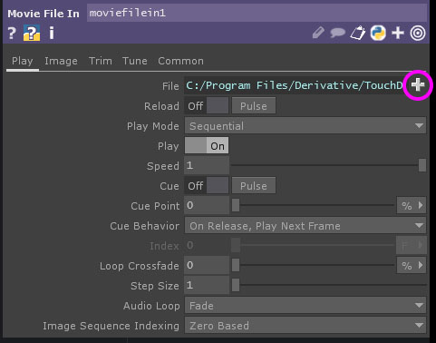
①Movie File at the Top
The “Movie File In” tab allows you to load video and image files. Click the “+” button to the right of the “File” field shown below to change the data to be loaded.
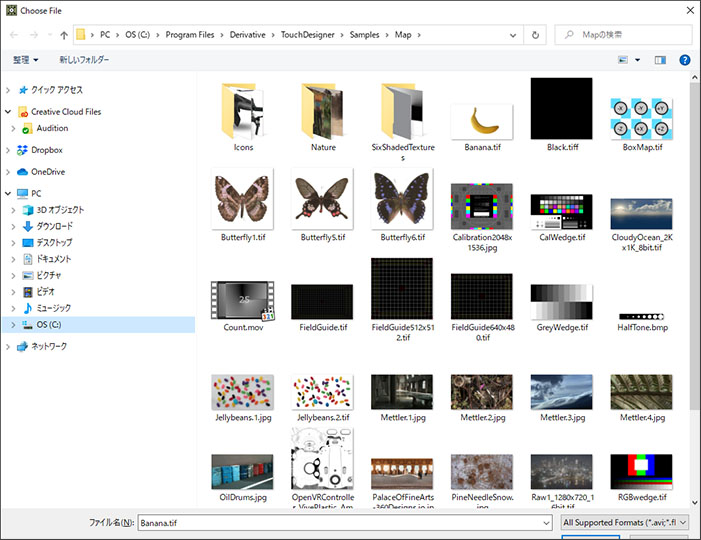
TouchDesigner comes with several sample images (see below) pre-installed. Please note that the NON-COMMERCIAL version has a maximum resolution limit of 1280×1280, so attempting to load data with a higher resolution will result in an error message.
②Transform TOP
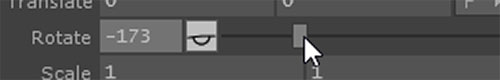
In the Transform panel, you can perform operations such as translation, rotation, and scaling. You can make changes by entering values in the fields shown below.
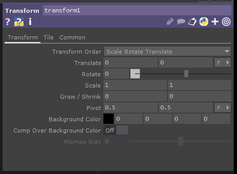
You can change the value of the Rotate slider by dragging with the left mouse button.
The method for changing values with the mouse in TouchDesigner is unique and takes some getting used to. First, click the mouse scroll wheel (the middle button) while hovering over a specific numeric field (the Rotate field in the image below).
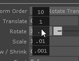
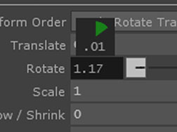
A menu like the one shown above will appear. To adjust the value, hold down the scroll wheel, move the cursor over the unit (10, 1, 0.1, 0.01, 0.001), and drag it horizontally.
13. Parameter Links
In TouchDesigner, you can generally only wire operators within the same family (though this may vary depending on the COMP’s configuration). Here, we’ll explain how to pass values from a CHOP to a TOP. This method is called a link or parameter link.
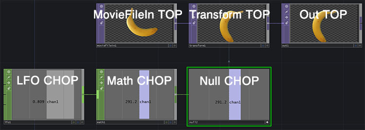
1. Adding LFO CHOP
In addition to the three operators mentioned above, add an LFO CHOP.
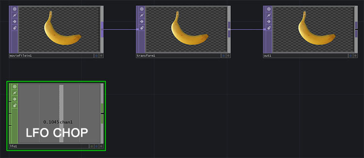
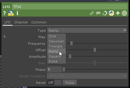
The LFO CHOP outputs a value that changes at fixed intervals. Initially, the Type is set to “sine,” but here we will change it to “ramp” (see figure below).
2. Adding the Math CHOP
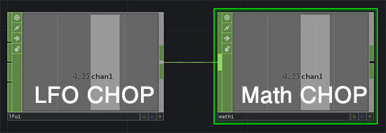
Add a Math CHOP and connect the output of the LFO CHOP to the input of the Math CHOP.
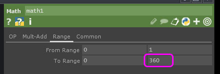
Math CHOP performs operations on multiple values (channels) and performs range transformations, among other functions. Here, as shown in the figure below, change the maximum value in the “To Range” field on the Range tab to 360.
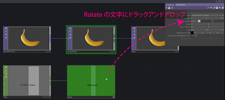
3. Link from Math CHOP to the Rotate property of the Transform TOP
Click the + in the bottom-right corner of Math CHOP to activate it.
Select “Transform TOP” to change the parameter to “Transform TOP.” Drag from “LFO CHOP” and drop onto the “Rotate” parameter.
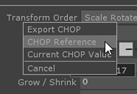
The menu shown below will appear; select “CHOP Reference.”
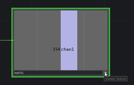
I was able to create an animation of a spinning banana. The linked state is indicated by a dotted line.
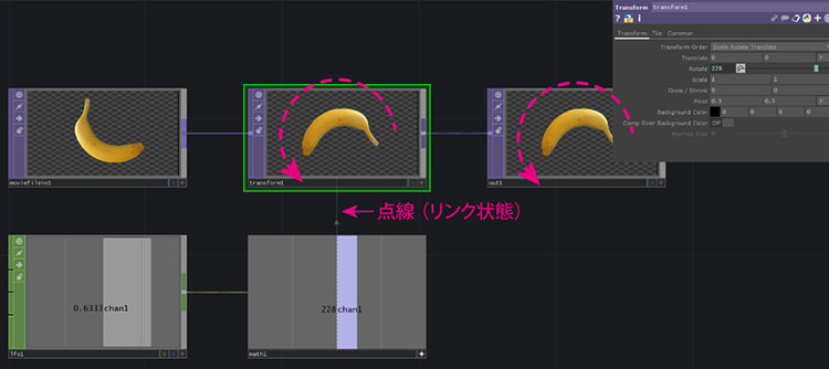
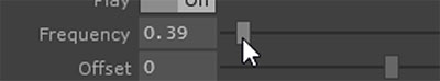
If the rotation speed is too fast, lower the Frequency setting for LFO CHOP.
14. Using the Null Operator
All six operators, excluding the Custom operator, have a Null operator. The Null operator has no functionality of its own; it simply outputs the value it receives.
For example, when passing values to different types of operators, using null at the end of a flow ensures that any changes made within the flow do not affect value references or similar operations. Using null when constructing nodes allows for more efficient programming.
15. Displaying the Backdrop During Processing
You can display the status of each operator in the background of the Network Editor. This allows you to experiment while comparing and verifying the processing steps.
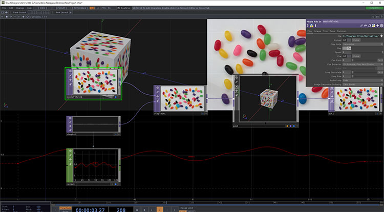
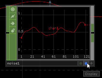
Press the blue button in the lower-right corner of the operator (see figure below) to display it in the Backdrop. You can also display the states of multiple operators. In that case, the background will automatically be divided to show them.
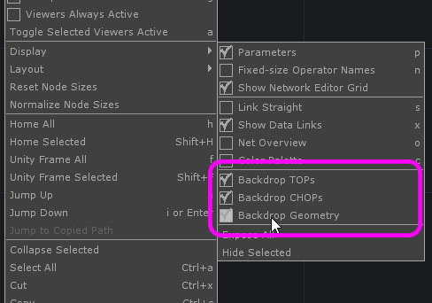
By default, only TOP and CHOP are displayed. To display Geometry, right-click the Network Editor and select “Backdrop Geometry” from the menu that appears (see figure below).
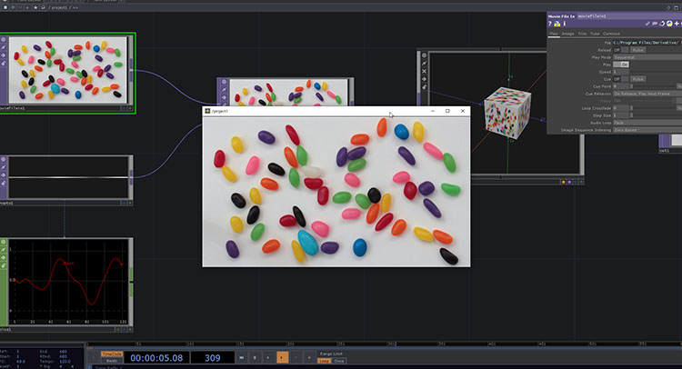
16. Displaying the Final Output (Out TOP)
Use “Out TOP” for the final processing results. As mentioned earlier, you can view “Out TOP” by displaying it on the Backdrop, but you can also display it in a separate window or in full-screen mode.
1. View via the Viewer
Click the “Open Viewer” button (white square icon) in the upper-left corner of the Network Editor (see figure below).
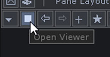
The results of the Out TOP operation are displayed in a separate window. The window can be resized.
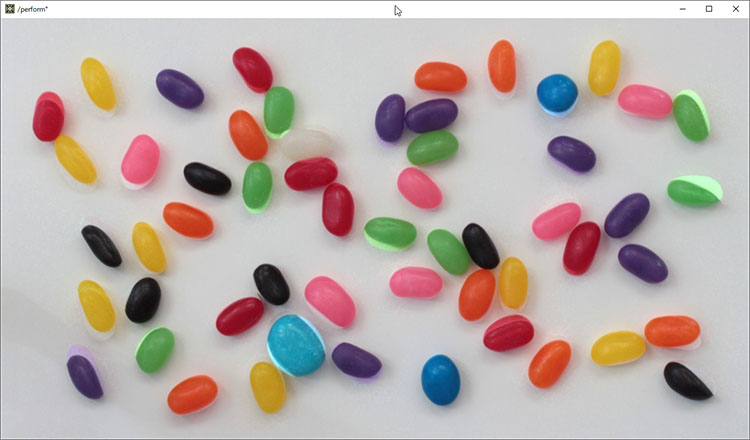
2. Display in Perform Mode
The mode you use for editing in the Network Editor is called Designer Mode; when giving a presentation using a projector or similar device, you should switch to Perform Mode. Switching to Perform Mode optimizes the system for faster processing.
To switch to Perform Mode, press the F1 key (or Fn + F1, depending on your system). To return to Designer Mode, press the ESC key. By default, the Border (top bar) is displayed in the Perform Mode window.
To hide the border and display the screen in full-screen mode, navigate to the root of the Network Editor (see figure below) and change the settings for Window COMP (name: perform).
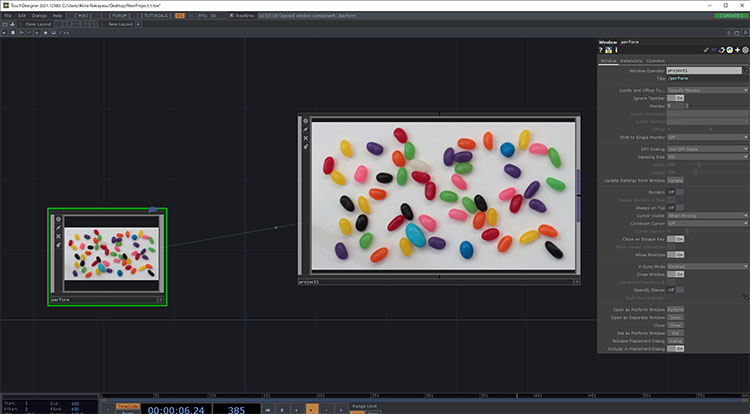
Set “Opening Size” to “Fill” and “Borders” to “off” to display in full screen.
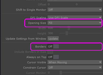
You can set the resolution of the output image using the Width and Height options on the Layout tab of the Container COMP (named “project1”). Under the Non-Commercial license, the maximum resolution is 1280×720.
17. Saving and Opening Project Files
1. Saving the Project File
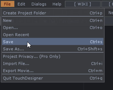
Select File > Save or Save As. Project files are saved with the .toe extension (a TouchDesigner Environment file).
When a project becomes large or involves collaboration among multiple people, you can use Project Folders or .tox files, which allow you to save only a portion of your node structure as a separate component.
2. Open the project file
After launching Touch Designer, select File > Open or Open Recent. When you do so, any projects that are currently open will be closed before the specified file is opened.
You can also double-click the .toe file to open it directly.