RealityCapture
1. What is RealityCapture?

https://www.capturingreality.com/
RealityCapture is photogrammetry software that generates 3D models by estimating camera positions (distance and angle) from multiple photos taken of the same subject.It supports photo analysis, laser scanning, and UAV (Unmanned Aerial Vehicle, commonly known as drones) surveying. Compared to other photogrammetry software, it can generate high-quality 3D models. Due to its advanced features, it may seem somewhat complex at first. However, information in Japanese is gradually becoming more available online.
RealityCapture, sold by CapturingReality, can be confusing because the company name and the software name are so similar. In March 2021, the company was acquired by Epic Games, the developer of Unreal Engine. Since the acquisition, the pricing has been significantly revised (making it more affordable), and the company has also begun offering free Academic licenses (available only to faculty members upon registration).
2. Types of Licenses
PPI / ENTERPRISE
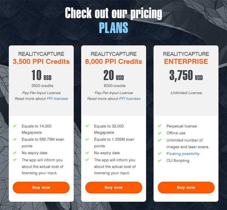
As of October 2021, RealityCapture offers two licensing options: PPI (Pay-Per-Input, based on the number of processes) and ENTERPRISE (one-time purchase).
- PPI 3,500 credits: 10 USD
- PPI 8,000 credits: 20 USD
- ENTERPRISE: 3,750 USD
In the PPI version, you can use all features except for exporting even before purchasing credits. You will need to purchase PPI credits when exporting. Project files are not compatible between the PPI and ENTERPRISE versions.
Please note that RealityCapture cannot be used simply by installing it; you must also create an Epic Games account. This is not required when using the Academic version token.
ACADEMIC Version
After RealityCapture was acquired by Epic Games, it began offering free licenses to educational institutions (prior to the acquisition, even the Academic version required a fee).
The ACADEMIC license is available only to universities and other academic institutions; individual students are not eligible to apply.
Announcement from CapturingReality: “We offer licenses through academic institutions. While we do not offer licenses directly to university students, we encourage you to recommend that your university apply for one.”
For this exercise, we will distribute the ACADEMIC licenses obtained by the university. The activation procedure is explained in the next section.
3. License Activation Using a Token
1. Downloading and Installing RelityCapture
https://www.capturingreality.com/
Go to the website above and click the “Download Now” button in the upper-right corner of the screen.

After downloading, double-click the installer to proceed with the installation.
2. Receiving Tokens
Distribute individual student tokens via Teams Messenger.
*Valid for 90 days from the start of use. If you wish to use it for personal projects after the course ends, you may do so by consulting with your instructor.
3. Activation via Token
Type “Command” in the Windows search bar to open the Command Prompt.
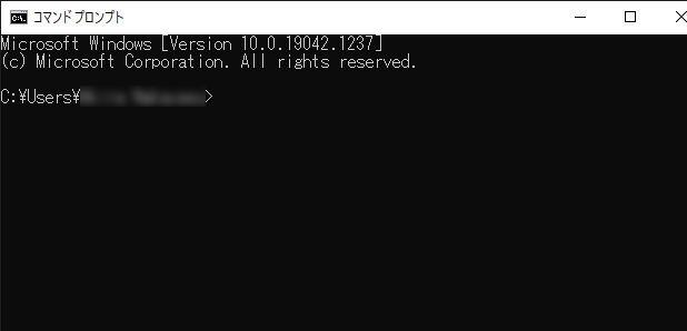
Enter the following after “>”.
“C:\Program Files\Capturing Reality\RealityCapture\RealityCapture.exe” -activate TOKEN
Delete the “TOKEN” part shown above, copy and paste the token you received, and press Enter.
4. Launching RealityCapture
Launch RealityCapture using a desktop shortcut or the search function.
The app will prompt you to restart it the first time you launch it after activation, so close it and then launch it again.
4. Using Tutorial Data
In this exercise, we will use the following two tutorial datasets. In particular, for ②, the settings for the Reconstruction Region and Ground Plane are important.
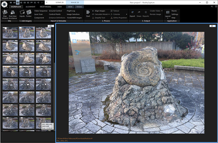
① Using the tutorial data from kuu-satsu.com
Download from the page at the URL below: “Smartphone Photos: 62 images (211 MB).”
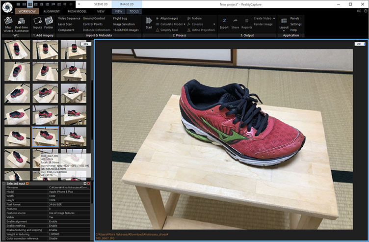
2. Use of Shoe Data (Photo by Nakayasu)
These will be distributed in class.
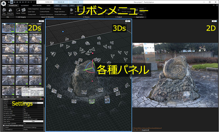
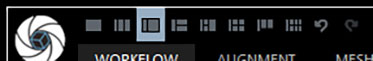
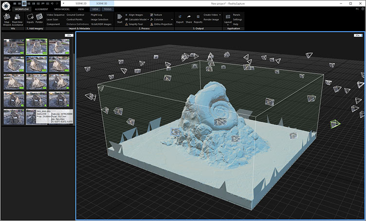
5. UI Overview
The ribbon menu is located at the top, and various panels are located at the bottom.
6. Switching UI Layouts
In RealityCapture, the UI layout changes as you progress through the different stages of the workflow.
Method 1: Switch using the icon in the upper-left corner
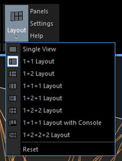
Method 2: Switch from WORKFLOW > Layout
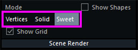
7. Switching Between Panel Views (View Types)
You can switch the panel’s display using the drop-down list in the upper-right corner of the panel.
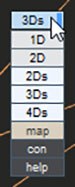
As for the 1Ds, it can only be displayed in the leftmost panel. Additionally, the leftmost panel can only display three types: 1Ds, 3Ds, and Help.

The following is a list of view types.
- 1D: textural information
- 1Ds: hierarchical relationships
- 2D: graphical information
- 2Ds: thumbnail view
- 3Ds: 3D information
- 4Ds: playing animations
- con: console
- map
- help
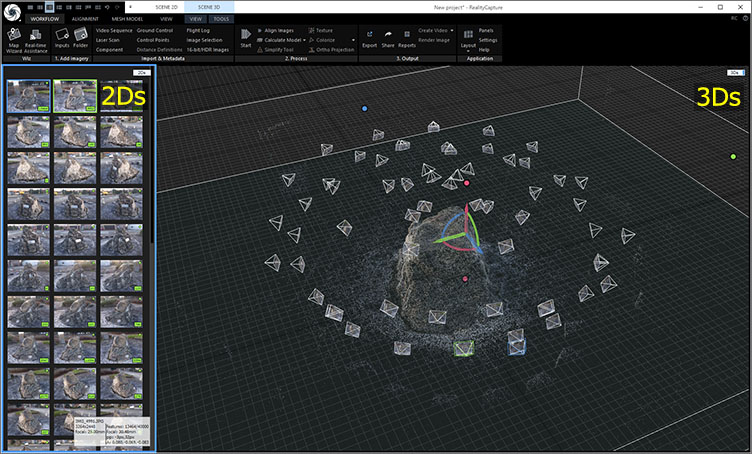
In this exercise, we will start with the following layout and panel display.
- Layout: 1+1
- Left panel: 2Ds
- Right panel: 3Ds
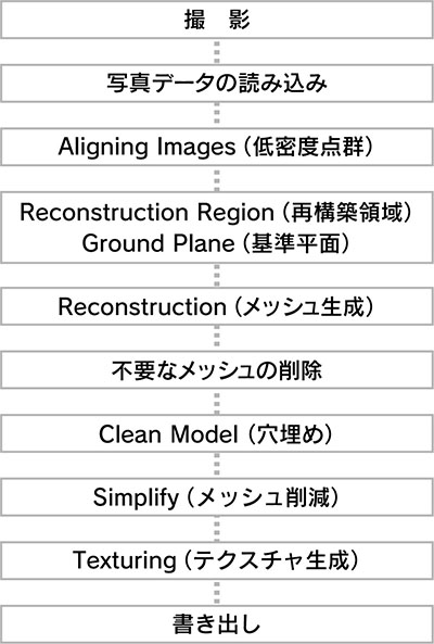
8. Workflow
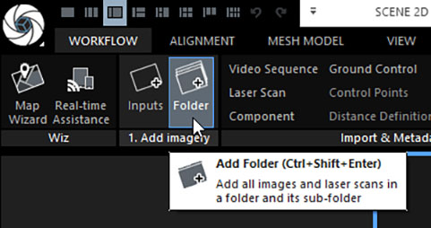
9. Importing Photo Data
WORKFLOW > 1. Click “Add imagery” > “Folder”.
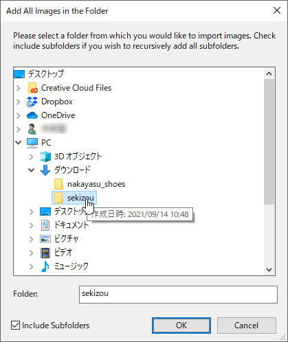
Select a folder and click OK.
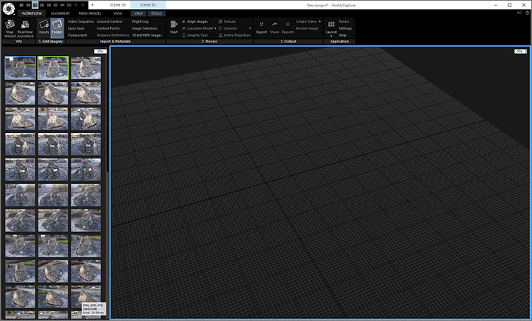
Thumbnails are displayed on the 2Ds (the left panel in the layout shown below).
10. Aligning Images (Low-Density Point Clouds)
In RealityCapture, the same tasks can be performed using different buttons (which can be a bit confusing). In particular, the WORKFLOW tab contains many duplicates because it organizes functions found in other tabs.
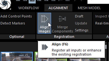
Method 1: ALIGNMENT > Registration > Align Images
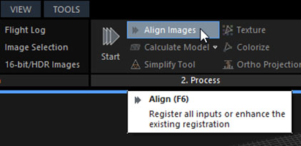
Method 2: WORKFLOW > 2. Process > Align Images
*Note: Do not use “Start” (batch processing) in this exercise.
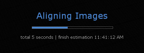
Processing time varies depending on the number of photos, resolution, and processing parameters. It may take anywhere from a few minutes to several tens of minutes.
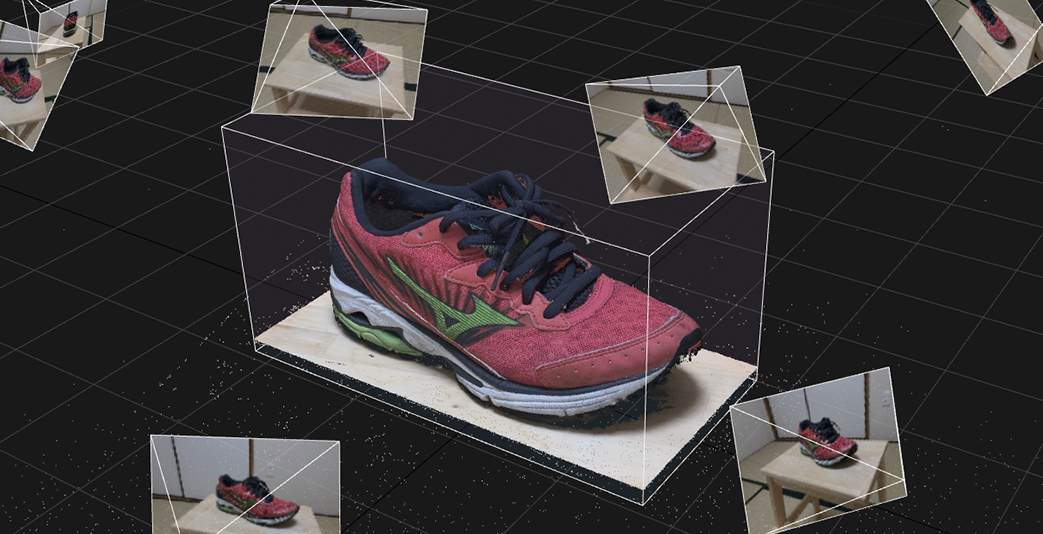
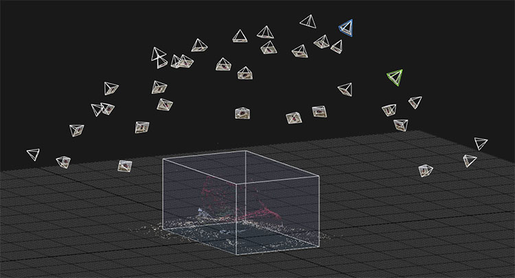
After processing, a low-density point cloud and camera preview (Alignment Cameras) are displayed.
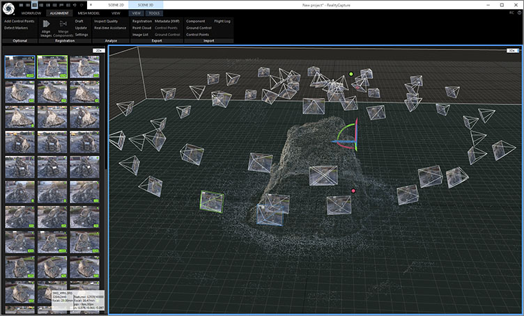
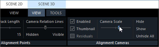
You can adjust the size of the camera preview and toggle the display of photo thumbnails using the UI shown below.
With the 3Ds panel open, go to SCENE 3D > VIEW > Alignment Cameras > Camera Scale, etc.
11. View Controls in 3Ds
Mouse Controls
- Left-click and drag: Move
- Right-click and drag: Rotate
- Scroll wheel: Zoom in/out
The rotation pivot (central axis) is located at the center of the grid. To rotate an object around this center, you must configure the Reconstruction Region and Ground Plane settings, as described later.
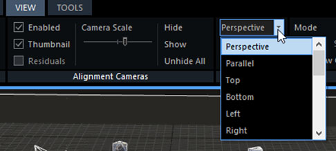
Changing the Viewpoint via the Menu
SCENE 3D > VIEW > View Camera > Select from the drop-down menu
*You’ll need to scroll to see the entire drop-down menu.
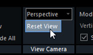
If the rotation axis is misaligned, resetting the view may resolve the issue.
Changing the View Using the Numeric Keypad (There seems to be a bug preventing this from working?)
- 0: Perspective
- 1: Parallel (Orthographic)
- 2: Top
- 3: Bottom
- 4: Left
- 5: Right
- 6: Front
- 7: Back
8 and 9 are unassigned
12. Reconstruction Region / Ground Plane
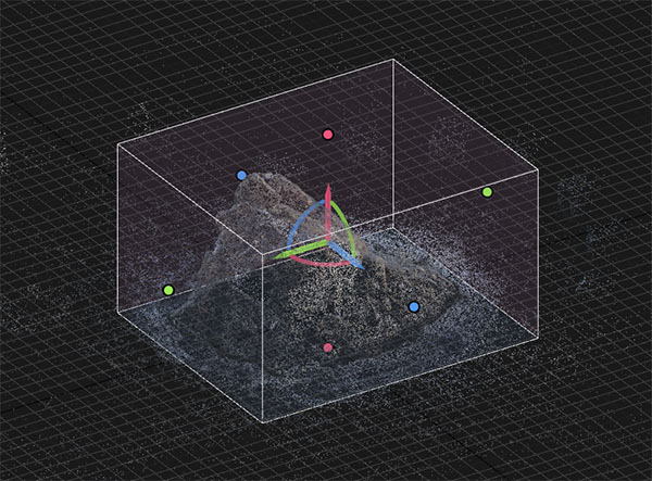
For tutorial data from kuu-satsu.com
In the low-density point cloud stage, the Reconstruction Region is set automatically, but it includes unnecessary areas. Since the Reconstruction (mesh generation) stage that follows is time-consuming, you should configure the Reconstruction Region to process only the areas you want to convert into a 3D model.
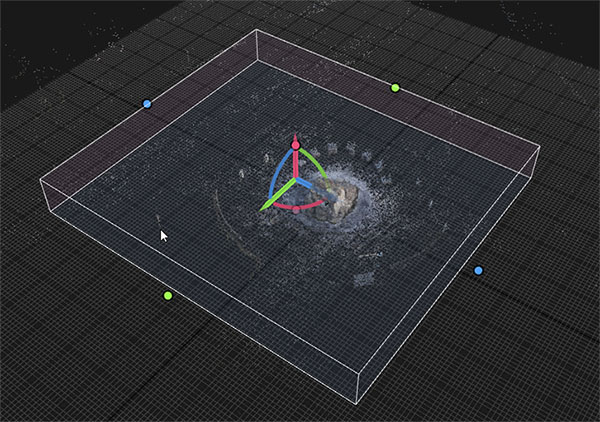
Use the colored controls to align the Reconstruction Region with the desired area. You may also use the Parallel (parallel projection) view.
Shoe Data (Photographed by Nakayasu)
In the case of shoe data, the horizontal alignment is significantly distorted in the low-density point cloud.
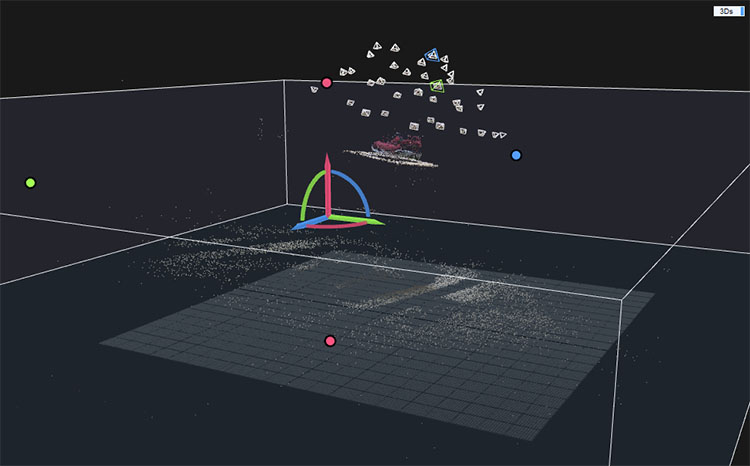
Use parallel projection to align the reconstruction region. This process requires some practice, so be patient as you make adjustments.
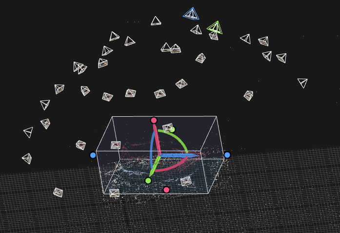
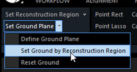
Once you have aligned the scene to a certain extent, click SCENE 3D > TOOLS > Scene Alignment > Set Ground by Reconstruction Region.
The Reconstruction Region is aligned with the origin of the grid.
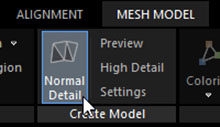
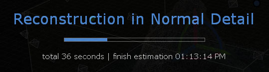
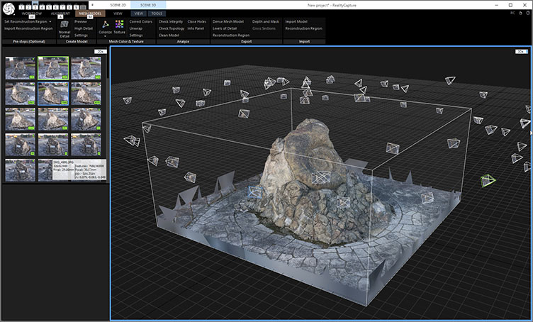
13. Reconstruction (Mesh Generation)
Click MESH MODEL > Create Model > Normal Detail.
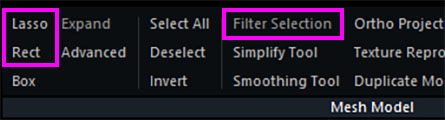
14. Deleting Unnecessary Meshes
This will not be covered in this exercise. It is used in body scanners.
- SCENE 3D > Mesh Model > Lasso, Rect, or Box (Select the mesh to delete)
- Filter Selection (Delete mesh)
15. Clean Model (Fill-in-the-Blanks)
This will not be covered in this exercise. It is used in body scanners.
*Note: In “Close Holes,” multiple holes may not be closed. (I don’t fully understand this yet.)
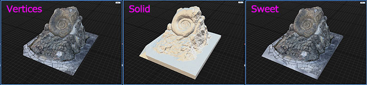
16. Texture Generation
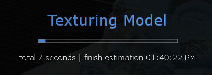
Click MESH MODE > Mesh Color & Texture > Texture.
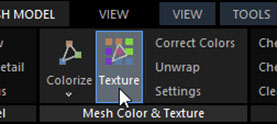
The texturing process begins.
17. Introduction
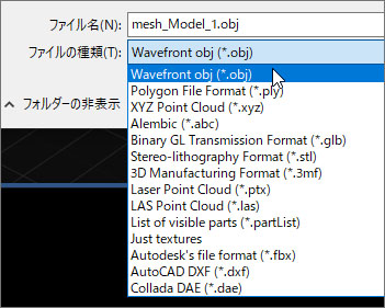
SCENE 3D (3Ds Panel) > TOOLS > Export > Mesh and Point Cloud

You can select the types of files to export, as shown in the figure below. Since multiple files, such as materials, will be exported, be sure to create a folder in the destination directory beforehand.
The “Settings” screen shown below will appear, but for now, click OK without making any changes.
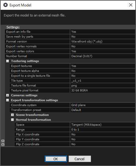
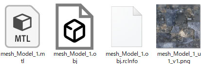
The following four files will be created. Since rcinfo is a log file, it is not needed outside of RealityCapture.